Included Parts
PCB

Pro Micro
Tactile Switch and TRRS Jack


Diodes

Acrylic Set

Hardware

Rubber Bump-ons

(RGB Kit) 510 Ohm Resistors

(RGB Kit) YS-SK6812MINI-E Leds

(RGB Kit) 0.1uF Capacitors

(RGB Kit) SSD1306 OLEDs
Please check the parts list before you begin.
| Name | Quantity | Notes |
|---|---|---|
| PCB | 2 | |
| Pro Micro | 2 | |
| Tactile Switch | 2 | |
| TRRS Jack | 2 | |
| Acrylic | 1 Set (6 pieces) | |
| M2 Spacer 7mm | 20 | |
| M2 Screws 6mm | 40 | |
| Rubber Bump-ons | 8 | |
| Diodes | 80 | 74 needed |
(Slice RGB) RGB Kit
| Name | Quantity | Notes |
|---|---|---|
| 510 Ohm | 2 | |
| 0.1uF Capacitors | 40 | |
| YS-SK6812MINI-E | 71 | |
| OLED | 2 |
Items Needed
| Name | Quantity | Notes |
|---|---|---|
| MX Compatible Keyswitches | 68-71 | 74 total keys |
| MX Keycaps | 68-71 | |
| TRRS Cable | 1 | 3.5mm Aux Cable |
| Stabilizers | 2-6 | GMK Screw-in or C3 recommended. Durock and Zeal stabilizer housings may be too big. |
Necessary Tools
| Name | Notes |
|---|---|
| Soldering Iron | Temperature-Controllable not necessary |
| Thin Solder | ~0.8mm diameter recommended |
| Tweezers | For SMD part assembly |
| Masking Tape | Optional |
| No-Clean Flux | Optional |
Building the Slice
🗹 (Optional) Pro Micro BMP Reinforcement with Epoxy Resin (as of 2/5/2021 Most pro micros sent are already reinforced)
- It takes some time to dry so let's do it first. Also, please read the instructions for drying time of the epoxy.
- Spread resin around the jack but make sure it does not enter.
- Make sure not to flow any into the usb jack of the pro micro.


🗹 Pro Micro Firmware
Pro Micros come pre-flashed with VIA Firmware.
Please refer to the following guide for flashing firmware.
🗹 Separate left and right sides
If not separated for shipping the boards will need to be separated.
- Fold the pcb's in on themselves to separate.
- Use a diagonal pliers or cutters to cut the excess.
- Sand down the pcb if needed.
🗹 Install diodes.
- It may be hard to see but if you look close the diode will have a direction.
- Line on the diode must go in the direction of the arrow as shown.
- If the diode is difficult to see look at it in a bright light or use a magnifying glass.
- If the diode is in the wrong direction the key will not work.
- Pre-solder one diode pad.
- With the tweezers in one hand and the iron in the other, place the diode. Melting the solder on the pre-soldered pad.
- Solder the other pad so both pads are soldered.
- Check from the side to see that the diode isn't floating and is flat against the pcb on both sides.

[embed width="320" height="240"]http://www.youtube.com/watch?v=QZMJhrPfYBk&t=0m31s[/embed]
Skip RGB Section
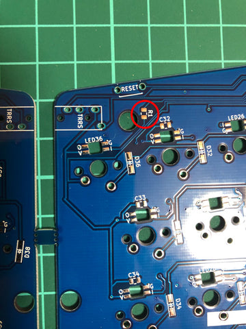
🗹 (RGB) 510 Ohm Resistors
- Install the 510 ohm resistors into R1 and R4 (no specific orientation)

🗹 (RGB) 0.1uF Capacitors
- Above half of the leds are 0.1uF capacitors, which have no specific direction. (See C66 in below image)
- Apply no-clean flux if necessary.
- Apply solder to one pad.
- Install capacitor.
- Apply solder to the other pad.
🗹 (RGB) LEDs
- No-clean flux recommended.
- Drag soldering recommended.
- These LEDs are chained, if one is not installed correctly the others will not work.
- Lower Temperature recommended.
- From the bottom view, align the notch (GND) to G on the pcb.
- Apply no-clean flux.
- Apply a small amount of solder to your iron.
- Drag the iron over one side while holding down the led with your tweezers.
- Drag the iron over the other side.


🗹 Install TRRS and Reset Switches
- Solder one hole of the TRRS jack and to make sure it is flush against the pcb.
- Reheat and push down on the jack to ensure it is flush with the pcb if necessary.
- Push the reset switches into place on the backside of the pcbs.
- Place the TRRS jacks and put masking tape over to prevent movement of the TRRS jack.
- Flip to the front side of the pcb to solder.


🗹 Install pro micros
- No-clean flux recommended.
- Pro Micro build is similar to the Helix or the Corne. See the Helix build guide here.
- Installing the orientation wrong or using too much force could lead to pins ejecting or pin bending.
- Removable pro micro tricks can work here too, you can look them up online incase you ever want to replace your pro micro.
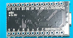
- Solder the spring loaded header to the pro micro, making sure the bottom side faces upward (Non-RGB, long side into the PCB)
- The smaller windows should be on the Pro Micro side. Also, install so both sets of headers have the small windows facing the same orientation.
- Insert the pro micro into the through-hole pads.
- It should lock into place without soldering, but I recommend soldering the other side.


Pro Microハンダ付け pic.twitter.com/2mIe6HFflE
— サリチル酸⌨️自キ温泉ガイド (@Salicylic_acid3) March 21, 2019
Skip RGB Section
🗹 (RGB) OLEDs
- Short the 4 jumpers on both pcbs. We are giving thanks to @foostan and others who helped trailblaze this design.
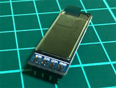
Tweet - Solder the risers into place. (Masking tape recommended)
- Solder the 4pin header onto the oled.
- Push the oled into the riser.


🗹 (RGB) Test LEDs (See LED Order Below)
- Test your work by plugging the usb into one half or the other half. See also the Corne Cherry Build Guide.
- If you plug in right hand only the last LED may not light up by default even though it's working. Test with both hands connected together.
- LEDs will all glow red if correctly soldered. You may have to go into VIA to turn on a solid color.
- You can toggle the leds on and off by hitting the bottom most left key.

🗹 LED Order and Reflowing LEDs
- If some are not glowing you'll need to reflow the LEDs
- LEDs are chained together in this order so you find the next LED in the chain to reflow.
- If after a few reflow attempts an LED happens to be bad (It happens) you may need to replace it all together. Use of an SMD rework station is recommended.

🗹 Test Board
- Test the board with a tweezers. Make sure all switches are functioning. Use the VIA key tester or another key tester to make sure.
🗹 Switches and Stabilizers
- Peel the top plate paper to reveal the clear acrylic on both sides of each board.
- Install stabilizers to the pcb first. Note Non-RGB Slice: Durock and Zeal stabilizer housings may be too big and not allow the acrylic to sit properly and the switches to sit firm to the pcb. GMK Screw-in are recommended.
- Set the top plate over the stablilizers.
- Insert the switches into the top plate. You may have to solder a few. The 3mm acrylic is big and it's okay if it is touching the pcb at this point.
- Solder the switches into place.
🗹 Acrylic Sandwich
- Screw the four 7mm or 10mm spacers to next to the pro micros for the oled/pro micro display protecting plate.
- Screw the 7mm spacers to the backplate.
- Screw the top plate screws into place to complete the sandwich case.
- Gently push down on the switches to even out the acrylic if necessary.
- Install the display protecting plate.
🗹 Add Bump-ons
- Install bump-ons